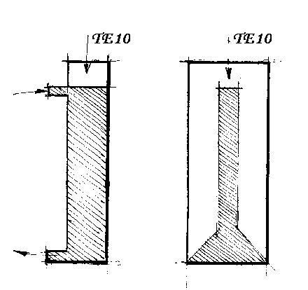
The microwave radiation produced by the magnetron is guided to the material being treated. The guide must therefore be selected according to the loss characteristics, shape and size of the material under treatment.Thus a material which is highly reactive to microwaves requires a travelling wave guide, whereas a less reactive (low loss) material requires the use of a standing wave guide. The choice of guide is therefore correlated with the material being treated if effective microwave treatment is required [4].
Heating water for which a strong microwave absorption occurs, requires therefore a travelling wave guide such as an elementary circular wave guide or preferably rectangular with an inner tube [5]. This is because the penetration depth of the microwaves ie. the inverse of the absorption coefficient of water has the same order of magnitude as the wavelength of the microwaves. The proposed heat transfer is illustrated by the two figures below.

Having chosen the microwave heat transfer principle, the design of both
the wave guide and the inner pipe depends upon the simplest manufacturing
process. If the wave guide and the inner tube constitute a unique piece
manufactured in a high performance technopolymer, a polysulfone for instance,
then the design will be rectangular because of a good flow and easy heat
transfer conception. Also we will use the TE10 mode, [6] for the electromagnetic
propagation because it permits an efficient coupling for the microwave
energy transfer with inherently non-radiating for the inlet and outlet
water [4].
The efficiency of the microwave water heater is entirely
determined by the efficiency of the magnetron which is
typicaly in the range 0.65 - 0.70.
| Optimum coupling
In the case of a rectangular wave guide we can use for instance the 2.45 GHz frequency with standard dimensions WR 340 a = 86.36 mm and b = 43.18 mm, the wave guide length L being calculated. |
|
Let us consider a liquid slab of thickness e and height b placed at the center of the wave guide because the electric field is maximum at this place with the TE10 mode.
If a is the microwave amplitude attenuation in dB/m (decibel per meter), the power attenuation after a distance of L will be 2aL then with the TE10 mode, [4], [7] :
2aL = 7.35 (2L) e e" dB
e" is the loss factor supposed temperature independent, e is in mm, L is in m.
In the case of water e" = 8.9 at 25°C, e" = 6 at 40° C and e" = 4.2 at 55°C
For L = 0.25 m and e = 1 mm we have with 1KW and 1 Litre/mn
For an inlet water at 25°C 2aL > 22 dB the outlet temperature is 40°C
For an inlet water at 40°C 2aL > 15 dB the outlet temperature is 55°C
The corresponding volume is approximately 0.01 litre. For a best absorption at elevated temperature one can increase the pipe width e, for instance to 5 or 10 mm , the corresponding volume will be 0.05 or 0.1 litre respectively. In the termination the pipe width is increased from e to a in order to absorb the residual microwave power.